TI 15.4-Stack Software Development Platform
TI’s royalty-free TI 15.4-Stack is a complete software platform for developing applications that require extremely low-power, long-range, reliable, robust and secure wireless star-topology-based networking solutions. This kit is based on the SimpleLink CC13x0 ultra-low power wireless microcontroller unit (MCU). The CC13x0 device combines a sub-1 GHz RF transceiver with 128KB of in-system programmable memory, 20KB of SRAM, and a full range of peripherals. The CC13x0 device is centered on an ARM® Cortex®-M3 series processor that handles the application layer, TI 15.4-Stack, and an autonomous radio core centered on an ARM Cortex-M0 processor, which handles all the low-level radio control and processing associated with the physical layer and parts of the link layer. The sensor controller block provides additional flexibility by allowing autonomous data acquisition and control independent of the Cortex-M3 processor, which further extends the low-power capabilities of the CC13x0 device.
Figure 2. shows the block diagram. For more information on the CC13x0, see the TI CC13x0 Technical Reference Manual.
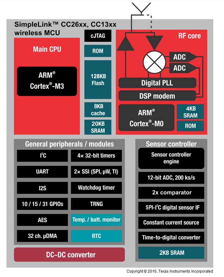
Figure 2. SimpleLink™ CC13x0 Block Diagram
Protocol Stack and Application Configurations
Figure 3. shows the two different system architectures enabled by TI 15.4-Stack.
- A single device is shown in Figure 3. (left). The application and protocol stack are both implemented on the CC13x0 as a true single-chip solution. This configuration is the simplest and most common when using the CC13x0 for network nodes and also using the CC13x0 as a personal area network (PAN) coordinator node. This configuration is the most cost-effective technique and provides the lowest-power performance.
- A coprocessor is shown in Figure 3. (right). The
protocol stack runs on the CC13x0 while the application is executed on an
external MPU or MCU. The application interfaces with the CC13x0 using the
network protocol interface (NPI) over a serial universal asynchronous
receiver/transmitter (UART) connection. The description of the API interface is
provided in the TI 15.4-Stack CoP Interface Guide document found in the
docs/ti154stackfolder of the SimpleLink CC13x0 SDK install. This configuration is useful for applications that must add long-range wireless connectivity or peripheral applications, which execute on another device (such as an external MCU) or on a PC without the requirement to implement the complexities associated with a wireless networking protocol. In these cases, the application can be developed externally on a host processor while running TI 15.4-Stack on the CC13x0, which provides ease of development and quickly adds long-range wireless connectivity to existing products.
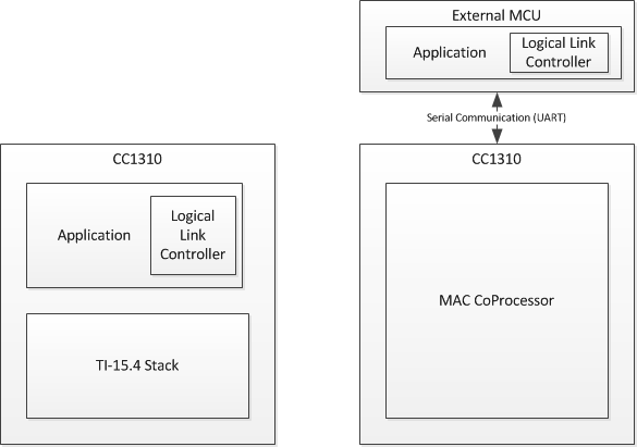
Figure 3. Single Device and Coprocessor Configuration
Solution Platform
This section describes the various components that are installed with the SimpleLink CC13x0 SDK, the directory structure of the protocol stack, and any tools required for development. Figure 4. shows the TI 15.4-Stack development system.
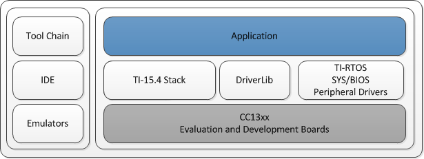
Figure 4. TI 15.4-Stack Development System
The following components are included in the solution platform:
- Real-time operating system (RTOS) with the TI-RTOS™ SYS/BIOS kernel, optimized power management support, and peripheral drivers (serial peripheral interface [SPI], UART and so forth)
- The CC13xxware driverLib provides a register abstraction layer that is used by software and drivers to control the CC13x0 MCU.
- TI 15.4-Stack is provided in library form.
- Example applications make the beginning stages of development easier. Example applications are provided for the CC13x0 platform and Linux® example applications are provided for the AM335x device running the processor SDK for Linux.
- Code Composer Studio™ (CCS) is the supported IDE for the example applications for the CC13x0 platform.
Directory Structure
The SimpleLink CC13x0 SDK installer includes all the files needed to start evaluating example applications and to later create custom applications using TI 15.4-Stack. The installed SDK provides the following content at the indicated default locations on the development computer:
Documents: detailed API, developer’s guide, and user’s guide documentation
C:\ti\simplelink_cc13x0_sdk_1_30_00_xx\docs\ti154stack
Examples: complete application examples for collector, sensor, and coprocessor devices, as well as prebuilt hex files.
If using a CC1310 then examples are here:
C:\ti\simplelink_cc13x0_sdk_1_30_00_xx\examples\rtos\CC1310_LAUNCHXL\ti154stack
If using a CC1350 then examples are here:
C:\ti\simplelink_cc13x0_sdk_1_30_00_xx\examples\rtos\CC1350_LAUNCHXL\ti154stack
Tools: support files for the Wireshark protocol analyzer
C:\ti\simplelink_cc13x0_sdk_1_30_00_xx\tools\ti154stack
Projects
The TI 15.4-Stack component within the SimpleLink CC13x0 SDK includes several projects that range from providing core IEEE 802.15.4 MAC functionality to use-case specific applications such as Collector and Sensor. The following projects can be used directly out of the box to demonstrate basic wireless applications and can be used later as a starting point for new application development.
The Coprocessor project can be used to build a MAC coprocessor device that works with a host processor in a 2-chip scenario. The coprocessor project provides full-function MAC capability over serial interface to the application running on the host. This device allows TI 15.4-Stack wireless functionality to be added to systems that are not suited to single-chip solutions. A prebuilt hex file for the coprocessor is provided in the SDK. If changes are needed, such as addition of a custom API command, the coprocessor project can be used to generate a new hex file.
The Collector project builds a full-function device (FFD) that performs the functions of a network coordinator (starting a network and permitting devices to join that network) and also provides an application to monitor and collect sensor data from one or more sensor devices. Prebuilt hex files for the collector project (demonstrating several communication scenarios) are provided in the SDK. The collector project is used to build these hex files and can be modified to alter communication or application functionality.
The Sensor project builds an reduced-function device (RFD) that performs the functions of a network device (joining a network and polling the coordinator for messages) and also provides an application to collect and send sensor data to the collector device. Prebuilt hex files for the sensor project are provided in the SDK to demonstrate operation in several communication scenarios. The sensor project is used to build these hex files and can be modified to alter communication or application functionality.
The _oad projects are used in conjuction with BLE OAD. These projects are functionally the same as the default sensor and collector applications except they exclude page 0 and page 31 in internal flash to make room for the BIM. For more information on BLE OAD see the Bluetooth Low Energy Software Developer’s Guide.
The Linux Collector and Gateway Applications are provided as part of the TI 15.4-Stack Linux SDK installer. The TI 15.4-Stack Linux SDK is a separate SDK that can be downloaded online at https://www.ti.com/tool/ti-15.4-stack-gateway-linux-sdk. The Linux Collector Example Application interfaces with the CC13x0 running the MAC coprocessor through UART. The Linux Collector Example Application provides the same functionality as the Embedded Collector Application with the addition of providing a socket server interface to the Linux Gateway Application. The Linux Gateway Application implemented within the Node.js® framework connects as a client to the socket server created by the Linux Collector Example Application and establishes a local web server to which the user can connect through a web browser (in the local network) to monitor and control the network devices. The Collector and Gateway Applications that provide IEEE 802.15.4 to the IP Bridge are a great starting point for creating Internet of Things (IoT) applications with TI 15.4-Stack.
The Linux Serial Bootloader Application is included inside the TI 15.4-Stack Linux SDK installer. This application demonstrates how to upgrade the firmware of the CC13x0 MCU through the CC13x0 ROM bootloader.
Note
Specific documentation for detailed Linux example applications can be
found in the ${linux_sdk_root}/doc folder after running the Linux
Installer.
The Linux installer requires an x86 64-bit machine running Ubuntu.
Setting Up the Integrated Development Environment
All embedded software for TI 15.4-Stack is developed using TI’s CCS on a Windows® 7 or later PC. To browse through the SDK projects and view the code as it is referenced in this document, it is necessary to install and set up the CCS integrated development environment (IDE). This section provides information on where to find this software and how to properly configure the workspace for the IDE.
Path and file references in this document assume that the SimpleLink CC13x0 SDK has been installed to the default path, hereafter referred to as <INSTALL_DIR>. Projects do not build properly if paths below the top-level directory are modified.
Installing the SDK
To install the SimpleLink CC13x0 SDK, run the installer: simplelink_cc13x0_sdk_1_30_00_xx.exe
Note
The xx indicates the SDK build revision number at the time of release.
The default TI 15.4-Stack install path is:
C:\ti\simplelink_cc13x0_sdk_1_30_00_xx\examples\rtos\CC1350_LAUNCHXL\ti154stack
(if using a CC1350) or
C:\ti\simplelink_cc13x0_sdk_1_30_00_xx\examples\rtos\CC1310_LAUNCHXL\ti154stack
(if using a CC1310).
In addition to TI 15.4-Stack code, documentation, and projects, installing the SDK also installs the TI-RTOS bundle and the XDC tools, if not already installed. Table 1. lists the software and tools that are supported and tested with this SDK. Check the TI 15.4-Stack Wiki for the latest supported tool versions.
| Tool Or Software | Version | Install Path |
|---|---|---|
| TI 15.4-Stack SDK | 2.1.0 | C:\ti\simplelink_cc13x0_sdk_1_30_00_xx\examples\rtos\CC13x0_LAUNCHXL\ti154stack |
| Core SDK | 3.01.00.14 | C:\ti\simplelink_cc13x0_sdk_1_30_00_xx\kernel\tirtos |
| XDC Tools | 3.50.00.10 | C:\ti\xdctools_3_xx_xx_xx_core |
| CCS IDE | 7.1 | C:\ti\ccsv7 |
| SmartRF™ Flash Programmer 2 | 1.7.5 | C:\Program Files (x86)\Texas Instruments\SmartRF Tools\Flash Programmer 2 |
Code Composer Studio
Code Composer Studio (CCS) provides a suite of tools that are used to develop applications that run on TI’s MCUs and embedded processors. CCS contains many features that go beyond the scope of this document—more information can be found on the CCS website. Check the CC13x0 SimpleLink SDK release notes to see which CCS version to use.
The following describes installing and configuring the correct version of CCS and the necessary tools.
- Download CCS 7.1 from the Download CCS wiki page.
- Launch the CCS installer.
- On the Processor Support menu (see Figure 5.), expand SimpleLink Wireless MCUs and select SimpleLink CC13xx and CC26xx Wireless MCUs
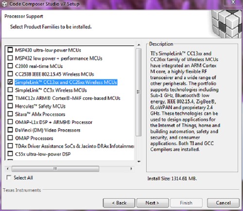
Figure 5. Processor Support Menu Selections
- Click the Next button, then click the Finish button.
- After CCS has installed, apply all available updates by selecting Help → Check for Updates.
Note
This step may require restarting CCS as each update is applied.
Configure CCS
This section explains how to configure CCS for development and debugging. It also provides information on useful CCS IDE settings (see Useful CCS IDE Settings)
Using CCS
This section describes how to open and build an existing project. The Sensor project is used as an example. However, all of the CCS projects included in the development kit have a similar structure.
Importing SDK Projects
Launch the CCS IDE and prepare to import the TI 15.4-Stack projects from the installed SDK:
Select Project → Import CCS Projects
Select Select search-directory: and click the Browse… button.
Navigate to
C:\ti\simplelink_cc13x0_sdk_1_30_00_xx\examples\rtos\CC1350_LAUNCHXL\ti154stack
and click the OK button (see Figure 6.). If using CC1310, navigate to
C:\ti\simplelink_cc13x0_sdk_1_30_00_xx\examples\rtos\CC1310_LAUNCHXL\ti154stack
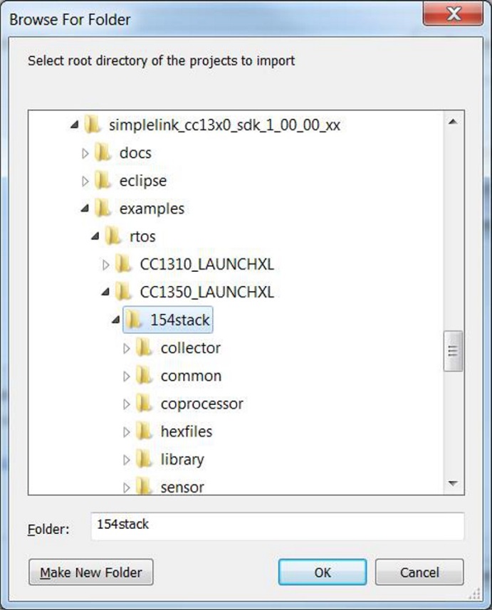
Figure 6. Import SDK Projects Menu Selection
The Discovered projects box now lists the projects that have been found. Select the Copy projects into workspace checkbox, click the Select All button, and last click the Finish button to import a copy of each SDK project into the workspace (see Figure 7.).
Note
In the following sections, the project names for the CC1310 and CC1350 platforms are referred to as CC13x0. Replace x with either 1 or 5 depending on the wireless MCU being used.
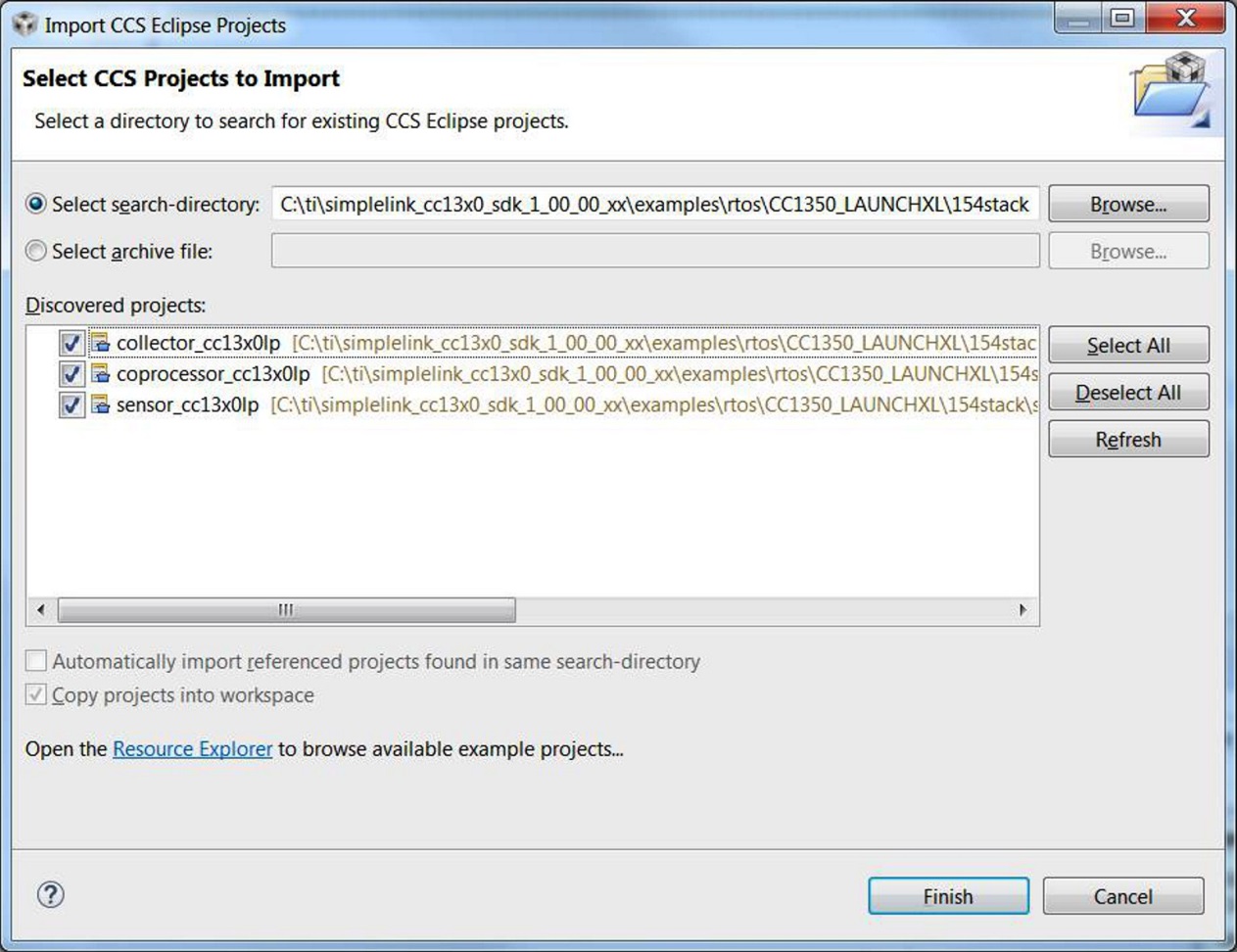
Figure 7. CCS Project Import Pane
Workspace Overview
The workspace now contains all projects needed to build downloadable images. The following examples build a Sensor image, to produce a functional sensor device.
In the Project Explorer pane, click on the sensor_cc13x0lp project to make
it active. Click on the arrow to the left of the project to expand its contents,
as shown in Figure 8..
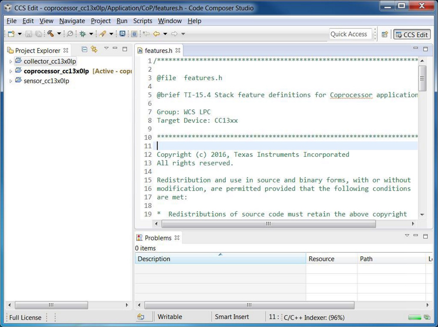
Figure 8. CCS Project Explorer Pane
In Figure 8., all folders (under the
sensor_cc13x0lp project) except for sensor_cc13x0lp can be
considered input folders, which contain source code files, header files, and
configuration files used to compile and link the application. The
sensor_cc13x0lp folder contains output files, which include programmable
images and the linker map.
Compiling and Linking
All example projects in the SDK are ready to build out-of-the-box meaning they are preconfigured for use with a specific target board, in this case the CC13x0 LaunchPad. To build a Sensor Application image that is ready to program onto a LaunchPad board, select Project → Rebuild Project. The Console pane of the IDE displays the individual results of source file compilations, followed by the linker results, as shown in Figure 9..
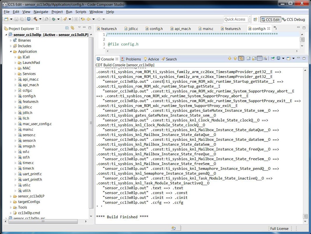
Figure 9. CCS Project Console Pane
In Figure 9., the output folder
sensor_cc13x0lp is populated with results from a successful build of the
Sensor Application. Two programmable output files have been produced,
sensor_cc13x0lp.out and sensor_cc13x0lp.hex, along with a detailed
linker map file, sensor_cc13x0lp.map.
Downloading Hex Files
As shown in Compiling and Linking, the CCS linker produces .hex files that are ready for direct download to the target hardware. The hex image can be downloaded to a target device by a stand-alone tool, such as the SmartRF Flash Programmer 2, shown in Figure 10..
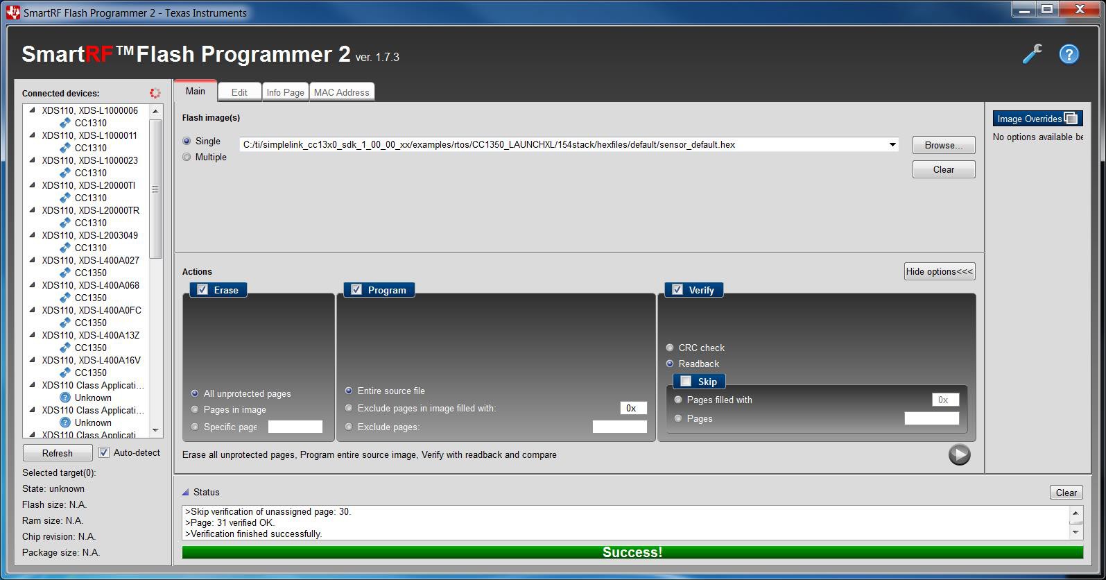
Figure 10. Programming Hex Files
As shown in Figure 10., SmartRF Flash Programmer 2 can be used to program the prebuilt hex file using the Flash image(s) → Single feature. Use the Browse… button to select the following files:
\examples\rtos\CC1350_LAUNCHXL\ti154stack\hexfiles\default\sensor_default.hex
After connecting a CC13x0 LaunchPad target board to one of the USB ports of the PC, the XDS110 instance becomes listed in the Connected devices panel. Select the listed device by clicking on the CC1310 icon. Programming the CC13x0 LaunchPad is accomplished through the following sequence (see Figure 10.).
- Select the Erase action, using the Pages in image option.
- Select the Program action, using the Entire source file option.
- Select the Verify action, using the Readback option.
- Press the Play button (blue icon at the lower right corner of the Actions panel).
- Observe the device programming feedback in the Status panel. It shows Success! when finished.
- Exit the SmartRF Flash Programmer 2 and power cycle the LaunchPad to run the application.
Debugging
When debugging is necessary, .out files produced by the linker are downloaded and run from the CCS IDE. The following procedure would typically be used to debug the program.
Continuing with the Sensor example project, the compiled program can be downloaded to the target and a debug session initiated by selecting: Run → Debug on the IDE, as shown in Figure 11..
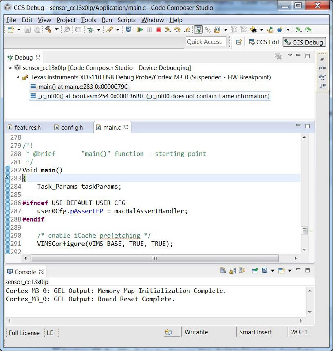
Figure 11. Debugging Sensor Application
In Figure 11., the IDE has switched from the CCS
Edit perspective to CCS Debug and shows the program counter stopped at main().
From this starting point, the developer can single-step through source
code, set and run-to breakpoints, and run the program using icons at the top of
the display. During a debug session, the user can switch between the CCS Edit
and CCS Debug perspectives, as necessary, to view project files and perform
debugging operations.
Useful CCS IDE Settings
The CCS provides a large number of configurable settings that can be used to customize the IDE and individual projects. The following examples do not alter the generated program code, but they can improve the developer’s experience when working with CCS projects. The CCS can reduce project compilation time by taking advantage of multiple processor cores on the development computer.
To use this feature, navigate to Project → Properties → Build → Behavior and select Enable parallel build, as shown in Figure 12..
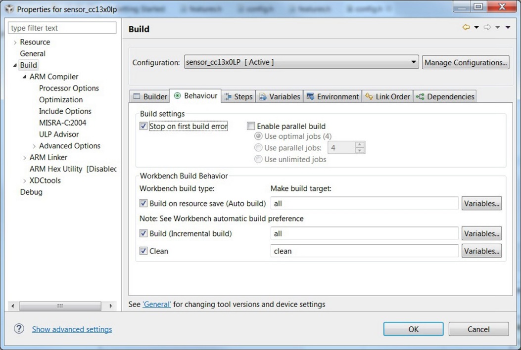
Figure 12. Properties for sensor_cc13x0lp
CCS users can control the amount of information that is displayed in the Console portion of the screen during project compilation and linking, ranging from Verbose to Super quiet. To change this setting, navigate to Window → Preferences → Code Composer Studio → Build and select an entry from the Console verbosity level drop-down, as shown in Figure 13.
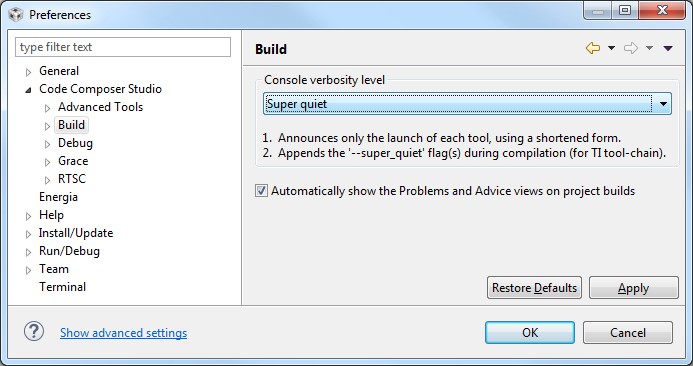
Figure 13. Console Verbosity Level Preferences
Accessing Preprocessor Symbols
Throughout this document and in the source code, various C preprocessor symbols may need to be defined or modified at the project level. Preprocessor symbols (also known as Predefined Symbols) are used to enable and disable features and set operational values to be considered when the program is compiled. A common way to disable an item without deleting it is to prefix an x to that item (see xASSERT_LEDS in Figure 14. for an example).
In CCS, preprocessor symbols are accessed by selecting and opening the appropriate Project Properties, then navigating to CCS Build → ARM Compiler → Predefined Symbols. To add, delete, or edit a preprocessor symbol, use one of the icons shown in the red box in Figure 14..
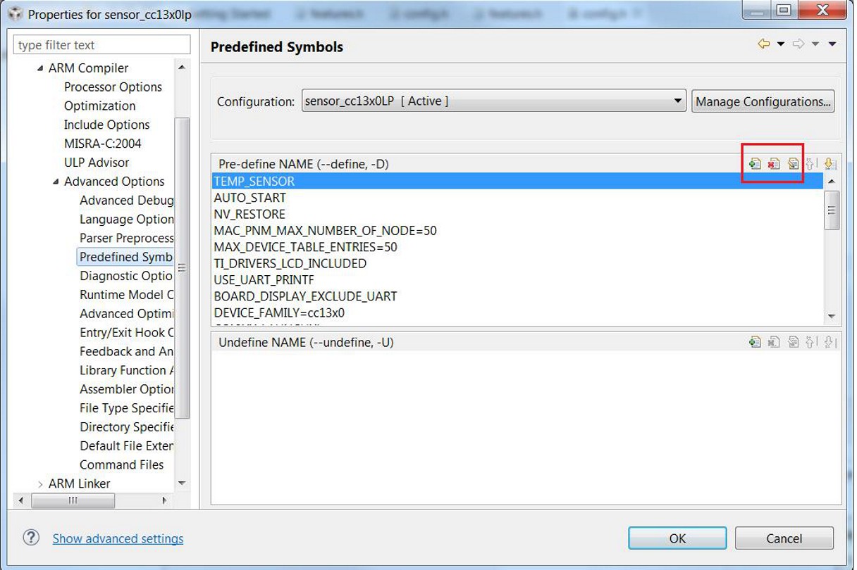
Figure 14. Predefined Symbols Pane
Top-Level Software Architecture
The TI 15.4-Stack software environment consists of three separate parts:
- A real-time operating system (RTOS)
- An Application
- A Stack
The TI-RTOS is a real-time, pre-emptive, multithreaded operating system that runs the software solution with task synchronization. Both the Application and MAC protocol stack exist as separate tasks within the RTOS, with the TI 15.4-Stack having the highest priority. A messaging framework, Indirect Call (ICall), is used for thread-safe synchronization between the Application and the Stack. Figure 15. illustrates the architecture.
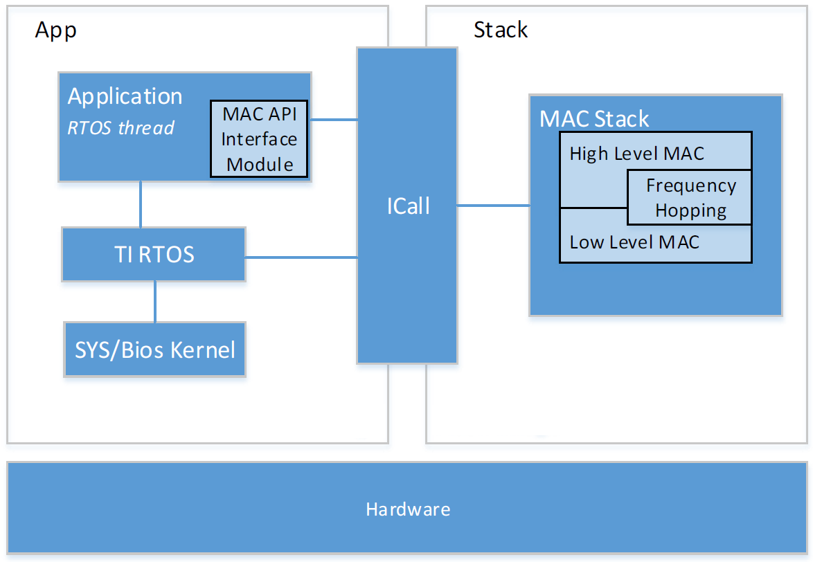
Figure 15. Software Architecture
- The Application
- Includes the application code, drivers, TI-RTOS, and the ICall module
- The Stack
- Includes the TI 15.4-Stack
- High-Level MAC is the API with the application, handles protocol messaging and data queues, controls the personal area network information bases (PIB).
- Frequency Hopping maintains frequency-hopping schedules and neighbor tracking.
- Low-Level MAC handles low level timing, encryption and decryption, and interfaces to the PHY.
Flash
The flash is split into erasable pages of 4 KB. The various sections of flash and the associated linker configuration file (cc13x0lp.cmd).
- Application space: contains example application (or your application), MAC stack, RTOS, drivers, and so on
- Nonvolatile (NV) area used for NV memory storage by the Application.
- Customer Configuration Area (CCA): the last sector of flash used to store customer specific chip configuration (CCFG) parameters
Using Nonvolatile Memory
Thetion NV area of flash is used for storing persistent data for the application.
TI 15,4-Stack provides two implementations of NV. One uses one page of internal
flash, while the other uses two. By default example applications use one page
NV. For more information on one page NV please refer to nvocop.c which
describes the implementation details. Also nvoctp.c describes the implementation
details of the two page NV. The last page in flash is the CCA page, depending
on whether one page or two page NV is used one or two pages before the last page (CCA)
are defined as the NV area. The example projects use the
NV driver with the API defined in nvintf.h.
The NV driver is set up in main.c:
#ifdef NV_RESTORE
    /* Setup the NV driver */
    NVOCTP_loadApiPtrs(&Main_user1Cfg.nvFps);

    if(Main_user1Cfg.nvFps.initNV)
    {
        Main_user1Cfg.nvFps.initNV( NULL);
    }
#endif
Then the applications use the function pointers in Main_user1Cfg to call the NV functions defined in nvintf.h:
//! Structure of NV API function pointers
typedef struct nvintf_nvfuncts_t
{
    //! Initialization function
    NVINTF_initNV initNV;
    //! Compact NV function
    NVINTF_compactNV compactNV;
    //! Create item function
    NVINTF_createItem createItem;
    //! Delete NV item function
    NVINTF_deleteItem deleteItem;
    //! Read item function
    NVINTF_readItem readItem;
    //! Write item function
    NVINTF_writeItem writeItem;
    //! Write existing item function
    NVINTF_writeItemEx writeItemEx;
    //! Get item length function
    NVINTF_getItemLen getItemLen;
} NVINTF_nvFuncts_t;
The following is an example of a write from csf.c:
static void updateDeviceListItem(Llc_deviceListItem_t *pItem)
{
    if((pNV != NULL) && (pItem != NULL))
    {
        int idx;
        idx = findDeviceListIndex(&pItem->devInfo.extAddress);
        if(idx != DEVICE_INDEX_NOT_FOUND)
        {
            NVINTF_itemID_t id;

            /* Setup NV ID for the device list record */
            id.systemID = NVINTF_SYSID_APP;
            id.itemID = CSF_NV_DEVICELIST_ID;
            id.subID = (uint16_t)idx;

            /* write the device list record */
            pNV->writeItem(id, sizeof(Llc_deviceListItem_t), pItem);
        }
    }
}
The following is an example of a read from csf.c:
bool Csf_getNetworkInformation(Llc_netInfo_t *pInfo)
{
    if((pNV != NULL) && (pNV->readItem != NULL) && (pInfo != NULL))
    {
        NVINTF_itemID_t id;

        /* Setup NV ID */
        id.systemID = NVINTF_SYSID_APP;
        id.itemID = CSF_NV_NETWORK_INFO_ID;
        id.subID = 0;
        /* Read Network Information from NV */
        if(pNV->readItem(id, 0, sizeof(Llc_netInfo_t), pInfo) == NVINTF_SUCCESS)
        {
            return(true);
        }
    }
    return(false);
}
The NV system is a collection of NV items. Each item is unique and have the following pieces to it (defined in nvintf.h).:
/**
*  NV Item Identification structure
*/

typedef struct nvintf_itemid_t
{
    //! NV System ID - identifies system (ZStack, BLE, App, OAD...)
    uint8_t systemID;
    //! NV Item ID
    uint16_t itemID;
    //! NV Item sub ID
    uint16_t subID;
} NVINTF_itemID_t;
Memory Management (RAM)
Space for RAM is configured in the linker configuration file (cc13x0lp.cmd). Application Image: RAM space for the Application and shared heaps. This space is configured in the linker config file of the Application, cc13x0lp.cmd
System Stack
Besides the RTOS and ICall heaps previously mentioned, there are other sections of memory to consider. As described in TI-RTOS Overview, each task has its own runtime stack for context switching. Furthermore, another runtime stack is used by the RTOS for main(), HWIs, and SWIs. This system stack is allocated in the Application linker file, to be placed at the end of the RAM of the Application.
For CCS, the RTOS system stack is defined by the Program.stack parameter in the app.cfg RTOS configuration file.
/* main() and Hwi, Swi stack size */
Program.stack = 1280;
Then the RTOS system stack is placed by the linker in the RAM space of the Application::
/* Create global constant that points to top of stack */
/* CCS: Change stack size under Project Properties */
STACK_TOP = stack + STACK_SIZE;
Dynamic Memory Allocation
The system uses two heaps for dynamic memory allocation. It is important to understand the use of each heap so that the application designer maximizes the use of available memory. The RTOS is configured with a small heap in the app.cfg RTOS configuration file.
var HeapMem = xdc.useModule('xdc.runtime.HeapMem');
BIOS.heapSize = 1724;
This heap (HeapMem) is used to initialize RTOS objects as well as allocate the TI 15.4-Stack task runtime stack. This size of this heap has been chosen to meet the system initialization requirements. Due to the small size of this heap, TI does not recommend allocating memory from the RTOS heap for general application use. For more information on the TI-RTOS heap configuration, refer to the Heap Implementations section of the TI-RTOS SYS/BIOS Kernel User’s Guide.
Instead, a separate heap must be used by the Application. The ICall module statically initializes an area of Application RAM, heapmgrHeapStore, which can be used by the various tasks. The size of this ICall heap is defined by the preprocessor definition of the Application HEAPMGR_SIZE, and is set to 0 by default for the Collector and Sensor projects; a value of 0 means that all unused RAM is given to the ICall heap. Although the ICall heap is defined in the Application project, it is also shared with the TI 15.4-Stack APIs which allocate memory from the ICall heap. To manually change the size of the ICall heap, adjust the value of the preprocessor symbol HEAPMGR_SIZE in the Application project to a value other than 0.
To profile the amount of ICall heap used, define the HEAPMGR_METRICS preprocessor symbol in the Application project. Refer to heapmgr.h in Components\applib\heap for available heap metrics. The following is an example of dynamically allocating a variable length (n) array using the ICall heap.:
//define pointer
uint8_t *pArray;

// Create dynamic pointer to array.
if (pArray = (uint8_t*)ICall_malloc(n*sizeof(uint8_t)))
{
    //fill up array
}
else
{
    //not able to allocate
}
The following is an example of freeing the previous array.:
ICall_free(pMsg->payload);
A Note on Initializing RTOS Objects
Due to the limited size of the RTOS heap, TI strongly recommends that users construct and not create RTOS objects. To illustrate this recommendation, consider the difference between the Clock_construct() and Clock_create() functions. Listing 1. shows the definitions of these functions from the SYS/BIOS API.
// Allocate and initialize a new instance object and return its handle
Clock_Handle Clock_create(Clock_FuncPtr, UInt timeout,  \
    const Clock_params *params, Error_Block *eb);

// Initialize a new instance object inside the provided structure
Void Clock_construct(Clock_Struct *structP, Clock_FuncPtr clockFxn, \
    UInt timeout, const Clock_Params *params);
By declaring a static Clock_Struct object and passing this object to Clock_construct(), the .DATA section for the actual Clock_Struct is used, not the limited RTOS heap. Conversely, Clock_create() causes the RTOS to allocate Clock_Struct using the limited heap of the RTOS. As much as possible, this method is how clocks and RTOS objects in general, should be initialized throughout the project. If creating RTOS objects must be used, the size of the RTOS heap may need to be adjusted in app.cfg.